Anyone testing antennas, wireless modules, or RF devices eventually runs into the term anechoic test box. It shows up in datasheets, lab requirements, and compliance checklists, but the definition is rarely spelled out. This guide explains what an anechoic test box is, how it works, what goes into building one, and where it fits next to a full anechoic chamber.
What Is an Anechoic Test Box?
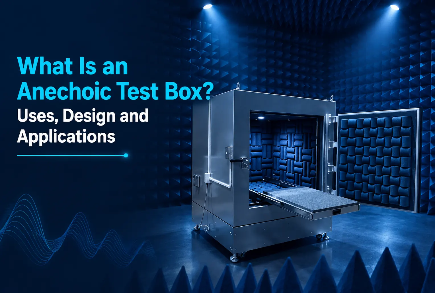
An anechoic test box is a compact, shielded enclosure lined with RF-absorbing material that creates a controlled, reflection-free environment for testing antennas, wireless devices, and RF components. The enclosure blocks external electromagnetic interference from entering, and the internal absorbers stop RF energy from reflecting off the walls. The result is a miniature, self-contained version of the free-space conditions a full anechoic chamber provides, sized for a bench or a lab table instead of a room.
Difference Between Acoustic and RF Test Boxes
The word "anechoic" applies to two unrelated technologies, and the distinction matters when specifying equipment.
An acoustic anechoic box absorbs sound waves. It uses foam wedges shaped to trap and dissipate audible sound energy, and it serves audio testing, microphone calibration, and sound-level measurement. No metallic shielding is involved because the goal is sound absorption, not electromagnetic isolation.
An RF anechoic test box absorbs electromagnetic waves instead of sound. It combines a metal shielded enclosure with RF absorbers made from carbon-loaded foam or ferrite tile, and it serves antenna measurement, EMI/EMC testing, and wireless device evaluation. This guide covers the RF version, which is the type used in electronics and telecommunications testing.
How Does an Anechoic Test Box Work?
An anechoic test box works by combining two functions inside a single enclosure: keeping outside signals out, and preventing internal reflections. Both are required to get a clean, repeatable RF measurement.
Metallic Shielding
The outer structure is built from conductive metal, typically galvanized steel or copper-clad panels, welded or gasketed to form a continuous conductive barrier. This shielding attenuates external RF signals such as Wi-Fi, cellular, and broadcast interference, so the readings taken inside reflect only the device under test.
RF Absorbers
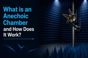
The interior walls are lined with RF absorbers, usually pyramidal foam or a foam-ferrite hybrid. These absorbers convert incoming electromagnetic energy into heat instead of letting it bounce back into the test volume. Pyramidal shapes work well across a broad frequency range because the graduated geometry reduces impedance mismatch at the absorber surface.
Reduction of Reflections and External Interference
Together, the shielding and the absorbers eliminate the two sources of measurement error that plague open-air RF testing: signals bouncing off nearby walls, floors, and equipment, and ambient RF noise from outside sources. Removing both variables is what makes the test repeatable.
Creation of a Controlled Test Environment
The combined effect is a controlled quiet zone where the only RF energy present is the signal radiated by the device under test. That is the baseline condition needed for accurate antenna pattern measurement, radiated emissions testing, and wireless performance validation.
Main Components
An anechoic test box is built from a defined set of parts, each serving a specific function in the shielding and absorption chain.
Shielded enclosure. The metal housing that forms the RF barrier. It is seam-welded or fitted with conductive RF gaskets at every access point to maintain continuous shielding effectiveness.
Pyramidal or foam absorbers. Lining the interior walls, ceiling, and floor, these absorbers suppress reflected energy across the box’s rated frequency range. Ferrite tiles are sometimes added at lower frequencies where foam alone is less effective.
RF connectors. Feedthrough connectors, typically N-type or SMA, pass signal cables through the shielded wall without breaking the shielding integrity. Each connector is fitted with EMI filtering at the panel to block leakage along the cable.
Antenna or DUT mounting system. A positioning fixture, sometimes a turntable or adjustable mount, holds the antenna or device under test at a fixed, repeatable location inside the quiet zone.
Ventilation and cable-access panels. Honeycomb waveguide vents allow airflow without compromising shielding, since the vent geometry is sized below the cutoff frequency for the box’s operating range. Cable-access panels provide a controlled path for power and data lines to reach the DUT.
Applications
An anechoic test box supports a wide range of RF and wireless testing tasks where a full-size chamber is unnecessary or impractical.
Antenna testing. Measuring gain, radiation pattern, and return loss on small to mid-sized antennas.
Wireless-device testing. Verifying radiated performance of handsets, modules, and embedded RF components.
Radar and RCS measurements. Small-scale radar cross-section evaluation on scaled targets or components.
EMI/EMC pre-compliance testing. Screening radiated emissions and susceptibility before sending a product to a certified compliance lab, catching design issues early and reducing the cost of formal testing.
IoT, Bluetooth, Wi-Fi and 5G device testing. Validating connectivity modules and short-range wireless components across their operating bands, including higher-frequency 5G designs.
Anechoic Test Box vs Anechoic Chamber
The core technology is the same, shielding plus RF absorbers, but the two differ in scale and application.
An anechoic test box is compact, benchtop or portable, and built for small devices, modules, and pre-compliance checks. It is faster to set up, lower in cost, and suited to R&D labs and production test floors where full chamber access isn’t practical for every measurement.
An anechoic chamber is room-sized, walk-in, and built for full compliance testing against standards such as CISPR and FCC Part 15. It accommodates larger DUTs, longer test distances, and larger quiet zones, and it is the environment required for certified compliance reporting.
Many labs use both: a test box for day-to-day development and pre-compliance screening, and a full chamber for final certification testing. For a full breakdown of chamber design and operation, see What Is an Anechoic Chamber and How It Works.
How to Select the Right Test Box
Choosing the right anechoic test box comes down to matching the box’s specifications to the testing task.
Frequency range. Confirm the box’s rated range covers every frequency band the DUT operates in, including harmonics if emissions testing is part of the plan.
Shielding effectiveness. Higher shielding effectiveness, expressed in dB, means better isolation from external interference. Applications sensitive to low-level signals need higher shielding ratings.
Quiet-zone size. The usable reflection-free volume inside the box must be large enough to keep the DUT and any antenna clear of the absorber surfaces.
DUT dimensions. The device under test, along with any fixtures or cabling, needs to physically fit inside the enclosure with clearance to spare.
Testing distance. Antenna measurements depend on maintaining a minimum distance between the antenna and the DUT for accurate far-field or near-field results. Box size should match the required test distance for the frequencies involved.
Customisation requirements. Connector types, turntable integration, camera ports, and cable routing all vary by application, and a box built for one test setup may need modification for another.
JV Micronics builds both portable anechoic chamber boxes and compact anechoic chambers configured to these specifications, along with standalone RF shielded enclosures for teams that need shielding without integrated absorber lining.
Frequently Asked Questions
What is an anechoic test box used for?
It is used for RF and EMC testing tasks such as antenna measurement, wireless device evaluation, and EMI/EMC pre-compliance screening, in a controlled environment free of reflections and external interference.
Is an anechoic test box the same as an anechoic chamber?
No. A test box is a compact, benchtop or portable version built for smaller devices and pre-compliance work. A chamber is room-sized and used for full compliance testing.
What materials are used inside an anechoic test box?
The interior is lined with RF absorbers, typically pyramidal foam or a foam-ferrite hybrid, mounted inside a shielded metal enclosure.
Can an anechoic test box replace a full compliance chamber?
It cannot replace certified compliance testing, but it is effective for pre-compliance screening and day-to-day development testing before a product goes to a certified lab.
What frequency range do anechoic test boxes cover?
Frequency range varies by model and absorber design. Boxes are built to cover specific bands from low MHz ranges up through multi-GHz 5G frequencies, so the range should be matched to the DUT’s operating bands.
Learn more about JV Micronics and its RF testing capabilities.