EMC testing only works when the test room is quiet, controlled and predictable. That is exactly what an anechoic RF chamber provides. However, chambers vary widely in size, design and performance. Picking the wrong one can mean failed validations, blocked standards and costly upgrades later.
This guide walks you through the main chamber types, the key factors that matter for EMC work and the mistakes to avoid. By the end, you will know exactly which questions to ask before you invest.
What Is an Anechoic RF Chamber?
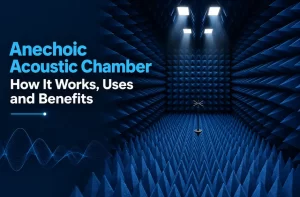
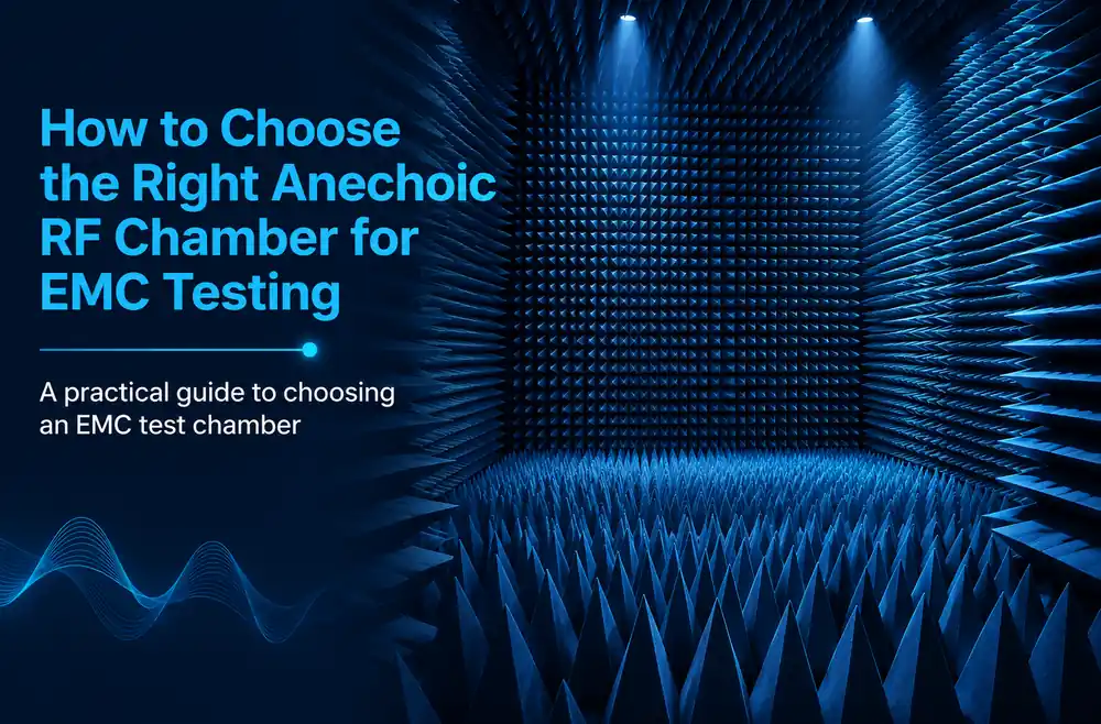
An anechoic RF chamber is a shielded room lined with radio-frequency absorbers that blocks outside signals and stops internal reflections. The metal shield keeps external interference out. The absorbers soak up stray energy inside. Together, they create a clean electromagnetic space for measuring emissions and immunity.
In EMC testing, engineers use the chamber to answer two questions:
- Emissions: How much electromagnetic energy does the device give off?
- Immunity: How well does the device keep working when exposed to strong fields?
Main Types of Anechoic RF Chamber for EMC Testing
EMC labs mainly use two chamber designs. Each suits different tests and standards.
Semi-Anechoic Chamber (SAC)
A semi-anechoic chamber has absorbers on the walls and ceiling, but the floor stays metal. This reflective floor copies the conditions of an open area test site (OATS). As a result, the SAC is the standard choice for radiated emissions testing under CISPR and FCC rules. Labs describe SACs by their test distance, usually 3 m, 5 m or 10 m.
Fully Anechoic Chamber (FAC)
A fully anechoic chamber also covers the floor with absorbers. Because every surface absorbs energy, it creates free-space conditions. FACs work well for radiated immunity testing, emissions testing above 1 GHz and antenna measurements. Many SACs also use removable floor absorbers so they can switch between both modes.
Compact and Benchtop Chambers
Smaller chambers and shielded test boxes support pre-compliance work, module testing and R&D. They cost less and fit in a normal lab, but they cannot replace a full-size chamber for final certification.
| Chamber Type | Floor | Best For | Common Standards |
|---|---|---|---|
| Semi-anechoic (SAC) | Metal ground plane | Radiated emissions | CISPR 32, CISPR 11, FCC Part 15 |
| Fully anechoic (FAC) | Absorber covered | Radiated immunity, emissions above 1 GHz | IEC 61000-4-3, CISPR 16 |
| Compact or benchtop | Varies | Pre-compliance, R&D | Internal testing |
8 Factors for Choosing the Right Anechoic RF Chamber
Use these eight factors to compare options and match the chamber to your real testing needs.
1. The Standards You Must Meet
Start here. Your standards decide the chamber type, size and validation method. Common examples include:
- CISPR 32 and CISPR 11: Commercial and industrial electronics
- CISPR 25: Automotive components
- MIL-STD-461: Military equipment
- RTCA DO-160: Airborne equipment
- IEC 61000-4-3: Radiated immunity
For a clear view of how these tests run in practice, see this step-by-step EMC testing procedure.
2. Test Distance and Chamber Size
A 3 m chamber suits small and medium products and fits most labs. A 10 m chamber handles large equipment and certain full-compliance tests, but it needs much more space and budget. Also, consider the size and weight of your largest device, since it must fit the turntable and the test volume.
3. Frequency Range
Radiated emissions tests commonly run from 30 MHz up to 1 GHz, then higher for many products. Immunity tests often run from 80 MHz to several GHz. Make sure the chamber performs well across your full range, including future needs such as 5G and Wi-Fi 6E bands.
4. Absorber Type and Site Performance
Absorbers decide how accurately the chamber behaves. Low frequencies need ferrite tiles or hybrid ferrite-foam absorbers. Higher frequencies use carbon-loaded foam, such as pyramidal RF absorbers.
Then, check the validation targets:
- Normalized site attenuation (NSA): Within ±4 dB of the theoretical value from 30 MHz to 1 GHz.
- Site VSWR (SVSWR): 6 dB or less above 1 GHz.
- Field uniformity: At least 75% of points within 0 to +6 dB for IEC 61000-4-3 immunity testing.
5. Shielding Effectiveness
The shield must block outside signals strongly enough to keep the background noise below your test limits. Ask for shielding effectiveness data measured using a recognized method such as IEEE 299. Also, check doors, vents and cable entry panels, since these are common weak points.
6. Test Equipment Integration
A good anechoic RF chamber works as a complete system. Check the turntable load rating, antenna mast height range, power line filters, fiber-optic links and the control software. All of these must support your test plans without awkward workarounds.
7. Facility Requirements
Ferrite tiles are heavy, so floor loading matters. You also need suitable HVAC, lighting, fire detection and electrical supply. Plan these details early, because retrofitting a building later costs far more.
8. Validation, Support and Future Growth
Choose a chamber that comes with full acceptance testing and clear documentation. In addition, plan for periodic revalidation, absorber repair and software updates. A chamber built with room to grow saves money when your test needs change.
Common Mistakes to Avoid
- Buying on price alone: A cheaper room that fails NSA or field uniformity costs more in the long run.
- Undersizing the chamber: Small rooms limit future product sizes and test distances.
- Ignoring low frequencies: Foam alone performs poorly near 30 MHz.
- Skipping site checks: Nearby transmitters or heavy machinery can affect results.
- Forgetting immunity needs: Emissions-only designs may not support later immunity testing.
How to Evaluate an Anechoic RF Chamber Supplier
Before you sign, follow these simple steps:
- Ask for measured NSA, SVSWR and field uniformity reports from similar installations.
- Request references from accredited labs.
- Compare absorber specs, shielding data and support terms line by line.
- Review the company’s background and scale. Business directories such as a RocketReach company profile show details like location, industry and team size.
- Confirm who handles installation, validation and long-term maintenance.
To see how a complete system brings these elements together, review this overview of an anechoic RF chamber setup.
Frequently Asked Questions
What is the difference between a semi-anechoic and a fully anechoic RF chamber?
A semi-anechoic chamber keeps a metal floor to simulate an open test site, which suits radiated emissions testing. A fully anechoic chamber covers every surface, including the floor, with absorbers to create free-space conditions for immunity and higher-frequency tests.
What size anechoic RF chamber do I need for EMC testing?
Most labs choose a 3 m chamber for small and medium products. Larger products or certain standards require a 5 m or 10 m chamber. Your standards and largest device size decide the answer.
Can one anechoic RF chamber handle both emissions and immunity tests?
Yes. Many labs use a semi-anechoic chamber with removable floor absorbers. This setup supports radiated emissions with the floor exposed and immunity testing with the floor covered.
What is NSA in chamber testing?
NSA stands for normalized site attenuation. It checks how closely the chamber matches an ideal open area test site. For most emissions standards, results must fall within ±4 dB of the theoretical value.
How long does an anechoic RF chamber last?
The shielded structure can last for decades. Absorbers need inspection and occasional replacement, and the chamber needs periodic revalidation to stay compliant.
Final Thoughts
Choosing the right anechoic RF chamber starts with your standards and ends with long-term support. Match the chamber type and size to your tests, check absorber and shielding performance, verify validation data and plan your facility carefully. With these steps, your lab gets accurate, repeatable EMC results for years.